
Thermal imaging system integration fails at the seams, not at the sensor.
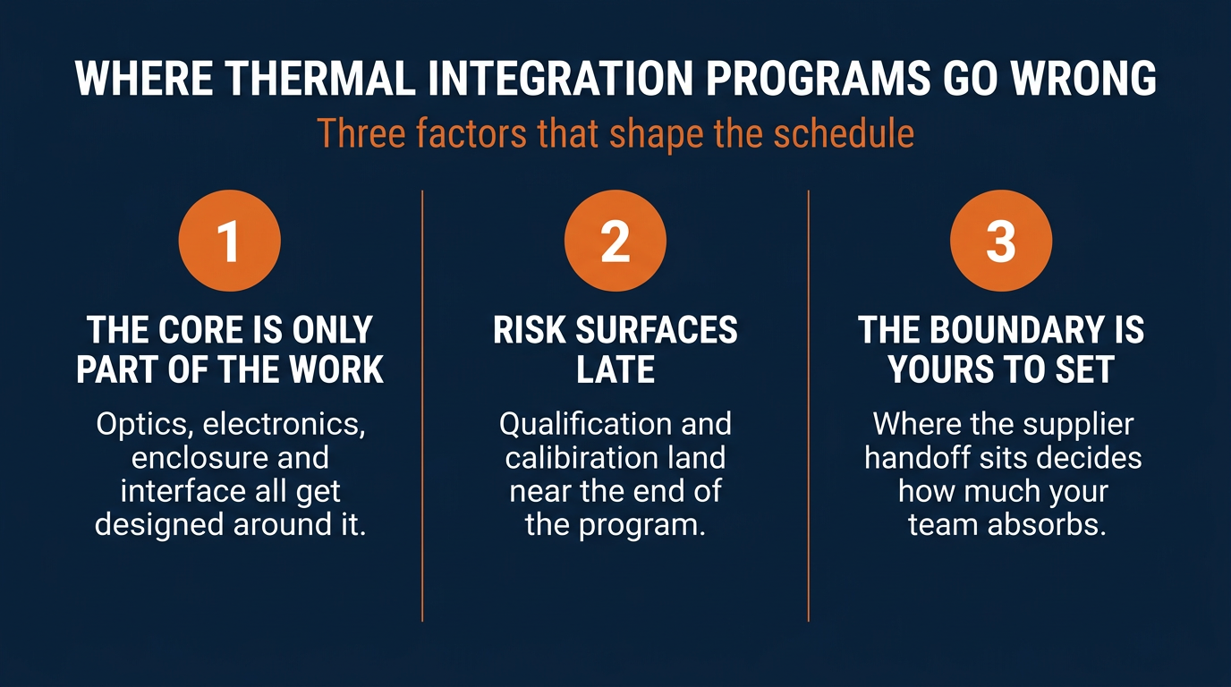
- The camera core is only part of the work. Optics, electronics, enclosure, and interface all have to be designed around it, and that engineering usually lands on the OEM.
- Integration risk shows up late. Environmental qualification and calibration happen near the end of a program, which is the worst possible time to discover a mechanical or thermal mismatch.
- Supply chain decisions made at the component stage constrain the platform for years. Material sourcing and compliance posture are locked in long before first article inspection.
- The supplier boundary is the variable you control. Where the handoff sits determines how much integration engineering your team absorbs.
If your team is treating thermal imaging as a purchasing decision rather than a system design decision, the schedule will eventually tell you otherwise.
Defense and industrial programs are getting longer, and the reasons are rarely exotic. In its most recent annual assessment of major weapon programs, the Government Accountability Office found the average time to deliver a capability has now stretched past twelve years, with programs repeatedly delaying key milestones and entering development carrying technology that was not yet ready. Sensor payloads sit right in the middle of that pattern. A thermal channel looks like a bounded procurement item on the program plan, and then it quietly becomes an integration project.
That gap between how thermal imaging system integration gets scoped and how it actually behaves is what this guide addresses. It is written for the people specifying full systems rather than evaluating handheld tools: program managers, systems engineers, and procurement leads building surveillance payloads, inspection platforms, and unmanned systems.
The decisions that hurt are almost never the ones about noise figures. They are the ones about scope, boundaries, and who owns what. The failure modes below recur across programs, and they are clearest from inside vertically integrated infrared manufacturing, where the whole chain from raw optical material to finished camera sits under one roof.
What Does Thermal Imaging System Integration Actually Involve?
Thermal imaging system integration is the engineering work required to turn an infrared imaging module into a functioning subsystem inside a host platform. It covers the optical path, the mechanical and thermal design, the power and processing architecture, the data interface, and the calibration and qualification activity that proves the whole assembly performs the way the program requires.
The distinction that matters most in any thermal camera integration effort is between a camera core and a camera system. A core is a component. It delivers image data through a defined interface and expects the host to handle nearly everything else. A system is a deliverable, arriving housed, sealed, calibrated, and characterized against a set of environmental conditions. Both are legitimate paths. What causes trouble is buying the first while planning as though you bought the second.
Where the Responsibility Boundary Sits
Every thermal imaging system design has a line where supplier responsibility ends and OEM responsibility begins. Moving that line changes your engineering headcount, qualification burden, and schedule far more than any single specification does. Teams evaluating options across a full thermal imaging solutions portfolio should map this boundary before comparing anything else.
|
Element |
Typically supplied with a core |
Typically owned by the OEM |
|---|---|---|
|
Detector and readout |
Supplier |
Supplier |
|
Lens selection and optical path |
Sometimes |
Often OEM |
|
Housing, sealing, mounting |
Rarely |
OEM |
|
Thermal management |
Rarely |
OEM |
|
Power conditioning |
Partial |
OEM |
|
Data interface and drivers |
Defined by supplier |
Implemented by OEM |
|
Environmental qualification |
Component level only |
System level, OEM |
|
Radiometric calibration |
Factory baseline |
Application specific, OEM |
Read that table as a staffing plan rather than a specification sheet. Each row in the right-hand column is engineering hours your program absorbs.

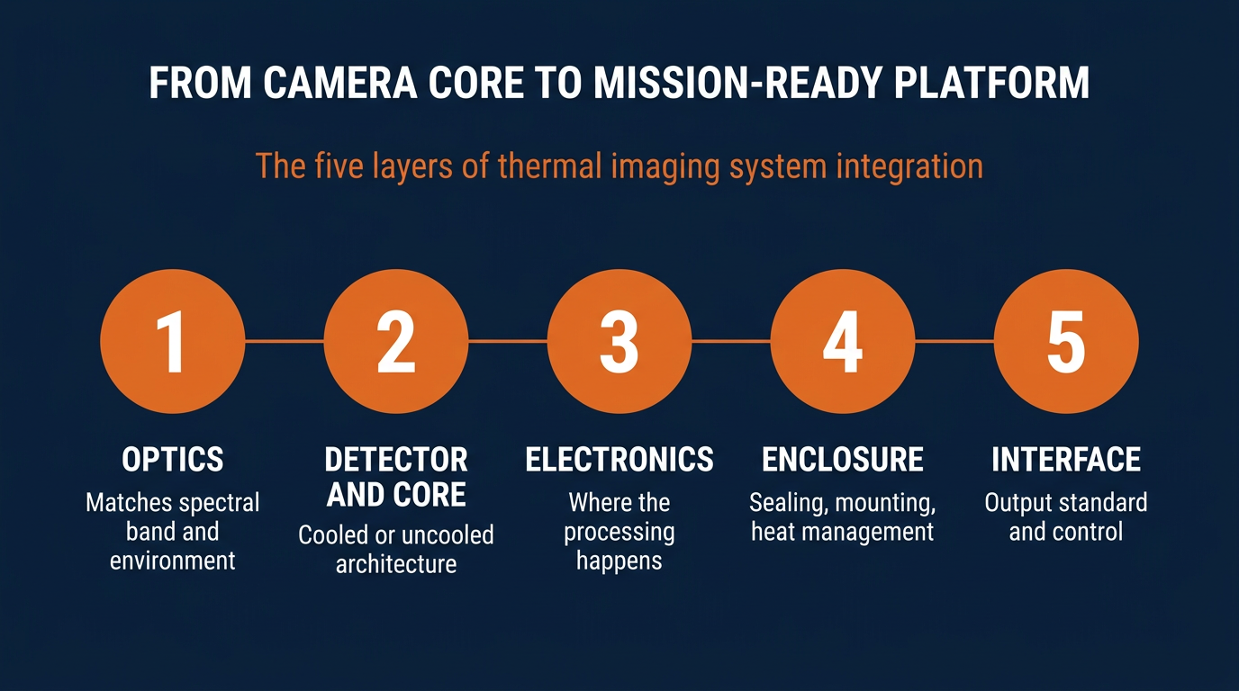
Which Five Elements Turn a Camera Core Into a Mission-Ready Platform?
Effective thermal imaging system design works outward from the detector in a specific order. Deferring a layer does not remove the work. It relocates the work to a later, more expensive point in the schedule. These five elements account for most of the integration effort on a typical OEM program.
- Optics. The lens defines what the detector can actually see, and it has to match both the spectral band and the operating environment. Long-wave systems working in the 8 to 14 µm range behave differently from mid-wave systems at 3 to 5 µm, and broadband infrared imaging systems covering 2 to 14 µm remove a refocusing step that would otherwise complicate the mechanical design. Optical material selection also carries supply chain consequences that outlast the design phase.
- Detector and core. Thermal camera core integration is where the cooled versus uncooled decision gets made, and it propagates everywhere. Cooled architectures bring cooldown time, additional power draw, vibration, and service life considerations. Uncooled architectures are lighter and simpler but need stable operating conditions to produce repeatable imagery. Neither is better in the abstract. The question is which one your total product architecture can carry.
- Electronics and processing. Image correction, video formatting, and onboard analytics have to run somewhere. Deciding whether that happens inside the imaging subsystem or on the host processor is one of the earliest infrared camera integration choices, and it changes cable design, latency, and software effort. Programs that defer it usually end up adding an adapter board late.
- Enclosure and thermal management. Enclosure work tends to get underestimated in infrared camera integration. A sealed housing traps heat, and imaging stability depends on managing it. Sealing, mounting, vibration isolation, and heat dissipation are one coupled problem. Solving them separately tends to produce a design that passes each individual test and fails the combination.
- Interface and control. The output standard has to match the downstream platform. Different interfaces carry different implications for cable length, bandwidth, electromagnetic compatibility, and driver work. The Department of Defense has pushed hard on this front, directing the services to implement a modular open systems approach so capabilities can be swapped and upgraded without redesigning the host. Interface choices made early determine whether your platform can take advantage of that.
Why Do Integration Problems Surface So Late in a Program?
Thermal camera integration issues cluster near the end of development for a structural reason. Optical, mechanical, electrical, and software work proceed on parallel tracks, and the first time they are genuinely tested together is during environmental qualification. Temperature cycling, vibration, shock, humidity, and electromagnetic compatibility testing evaluate the assembled system, not the components.
Calibration compounds this. A factory calibration reflects conditions in the factory. Once the module sits behind a specific window, inside a specific housing, at a specific operating temperature, its response changes. Programs that plan for one calibration event and then need application-specific characterization lose weeks they did not budget.
Requirements drift adds to it. Thermal performance targets often get written before the platform architecture settles, then quietly stop matching the enclosure the system shipped in. Reconciling that late is expensive, which argues for treating the OEM thermal imaging decision as an early architectural commitment. The build versus buy decision for OEM programs is fundamentally about when you absorb this risk.
The limits deserve equal honesty. Thermal imaging performs well in darkness, smoke, and haze, and it degrades in heavy rain, dense spray, and against very high radiance backgrounds. Qualification testing should reflect the conditions your platform will actually encounter.
How Should OEMs Evaluate a Thermal Camera Integration Partner?
Supplier evaluation for OEM thermal imaging tends to start with specifications and end with price. Both matter, and neither predicts integration outcomes well. The more useful questions are about capability depth and supply continuity.
Capability Depth
Ask what the supplier can actually change. A vendor who can adjust an optical design, modify a housing, or re-characterize a system for your operating envelope removes work from your team. A vendor who ships only from a catalog transfers that work to you. This difference never appears on a datasheet, though in OEM thermal imaging programs it tends to shape the schedule more than the specifications teams spend their time comparing.
Supply Continuity and Compliance
Infrared optics have a material problem. Germanium has long been the default substrate for infrared lenses, and China, the leading global producer, placed germanium under export licensing in 2023, after which reported exports of germanium metal fell sharply. For programs with multi-year production tails, alternative chalcogenide materials and domestic manufacturing are risk controls rather than preferences. Defense teams should confirm sourcing posture early, since NDAA compliance planning for defense programs is far harder to retrofit than to design in.
|
Evaluation area |
Component supplier |
Integration partner |
|---|---|---|
|
Design changes |
Catalog configurations |
Application-specific engineering |
|
Optical material control |
Purchased externally |
Produced in house |
|
Qualification support |
Component data only |
System-level test support |
|
Obsolescence handling |
Announced downstream |
Planned with the program |
|
Production continuity |
Subject to upstream sourcing |
Controlled internally |
|
Engineering engagement |
Transactional |
Program-length collaboration |
Industrial programs face a variant of the same problem. Continuous monitoring platforms run for years, and replacement units must behave identically to the originals. Teams building industrial thermal imaging platforms should weight production consistency as heavily as initial performance.
Frequently Asked Questions
Is a camera core cheaper than an integrated system?
The unit price is lower. The program cost frequently is not, because thermal camera core integration adds housing design, thermal management, interface implementation, and system-level qualification that the core price excludes. Compare fully burdened program cost, including the hours in the right-hand column of the responsibility table, rather than component cost alone.
What should an OEM ask a supplier before committing to a design?
Four questions separate real answers from sales answers. What in this design can you change for us, and what is fixed? Who owns system-level qualification? Where do the optical materials come from, and who controls that supply? And what happens to our program if this detector reaches end of life in year four?
How does integration change for size and weight constrained platforms?
Constrained platforms like unmanned aircraft compress every trade at once, so thermal imaging system design becomes a balancing exercise across power, mass, and volume. A small increase in one usually forces a reduction somewhere else. Broadband optical designs that avoid refocusing hardware, and uncooled architectures that skip the cooling assembly, both buy back margin that tightly packed payloads rarely have to spare.
What happens if a detector or core goes obsolete mid-program?
This is a common and expensive surprise on programs with long production tails. A replacement part with different dimensions, interface behavior, or spectral response can force requalification of the whole assembly, undoing the original thermal camera core integration work. Programs that survive it well either specified an open interface at the start or chose a partner controlling enough of the stack to manage the substitution without a platform redesign.
Design the System Before You Source the Parts
The programs that integrate thermal imaging well are the ones that decided early where the supplier boundary would sit, and then chose a partner capable of holding up their side of it. Infrared camera integration rewards that kind of upfront clarity and punishes the alternative, usually at the point in the schedule where there is no room left to recover.
LightPath Technologies builds across the full infrared stack, from proprietary Black Diamond chalcogenide glass through optical assemblies to complete cooled and uncooled camera systems. Domestic manufacturing, custom engineering, and support that runs the length of a program rather than ending at the purchase order all exist for one reason: to help client programs ship on schedule and compete harder once fielded. If you are scoping a thermal imaging system integration effort and want to work out where the boundary should sit for your platform, start a conversation with our engineering team.