Key Takeaways
OEMs and system integrators who approach industrial thermal monitoring as a system-level engineering challenge — not just a hardware selection decision — consistently deliver better-performing platforms and stronger long-term client outcomes.
- Environment and application planning before component selection prevents costly redesigns and ensures thermal monitoring systems perform accurately across real-world operating conditions
- Protocol compatibility and data architecture decisions made early in the design phase determine how well thermal monitoring integrates with SCADA, MES, and automation systems downstream
- Calibration discipline and baseline documentation are what separate functional deployments from truly reliable ones that deliver actionable data year over year
- According to the U.S. Department of Energy's Federal Energy Management Program, well-implemented predictive maintenance programs — thermal monitoring chief among them — deliver 30–40% savings over reactive maintenance approaches.
Demand for industrial thermal monitoring has moved well beyond early-adopter territory. Across manufacturing, energy, oil and gas, and utilities, OEMs are building thermal sensing into platforms that their customers depend on around the clock. The global thermal imaging camera market reached $4.12 billion in 2024 and is projected to reach $6.7 billion by 2032, with industrial predictive maintenance driving a significant share of that growth.
That trajectory creates opportunity — and it raises the stakes on getting integration right. A thermal monitoring system that underperforms in the field, fails to communicate with existing infrastructure, or drifts out of calibration reflects directly on the OEM who built it.
The most competitive platforms share something in common: they were designed from the start with thermal monitoring embedded into the system architecture, not bolted on at the end. Explore thermal imaging solutions for industrial applications to understand how component quality shapes that outcome.
What Does Successful Industrial Thermal Monitoring Integration Actually Require?
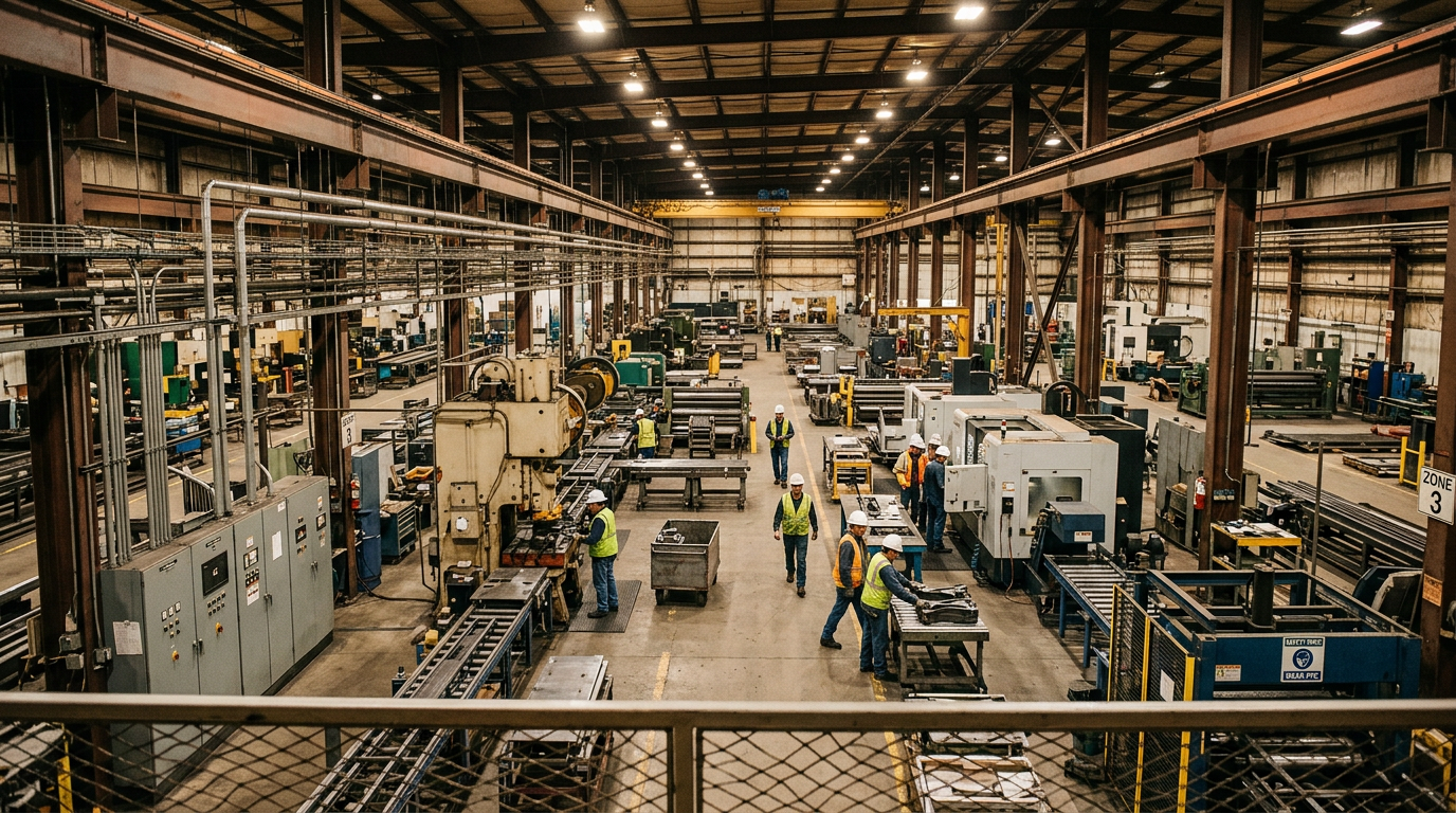
The temptation in many programs is to treat an industrial thermal imaging camera as a standalone component — specify it, install it, and move on. The problem is that thermal monitoring systems don't exist in isolation. They generate continuous data streams that need to flow somewhere, connect to protocols that need to match, and perform in environments that can be genuinely hostile to precision optics and electronics.
Integration success means thinking through the entire signal chain before a single component is specified. That includes where thermal data goes after capture, how it gets processed, and how the system responds when something anomalous is detected. OEMs who get this right deliver platforms that their customers trust. Those who don't spend the back half of a program chasing performance issues that were always going to emerge.
The Core Architecture Decisions
Data interface and protocol selection is where most industrial integration complexity begins. Modern industrial thermal imaging cameras support GigE Vision and USB3 for high-bandwidth video data, while industrial protocols like Modbus TCP, Profinet, and OPC-UA handle process-level communication with PLCs, SCADA systems, and MES platforms. The right combination depends on the application — a continuous monitoring system integrated into a plant DCS has different requirements than a mobile inspection platform — and those decisions need to happen at the system architecture stage, not during commissioning.
Edge vs. centralized processing is a second foundational choice. Edge processing at the camera or gateway level reduces network load and improves response time for alarm conditions, which matters when a thermal anomaly requires an immediate automated response. Centralized processing provides better historical analysis and trending capabilities. Many modern platforms use both: edge processing for real-time alerting, with full thermal data streamed to central storage for trend analysis and reporting.
Environmental protection and mounting rounds out the core architecture. An IP rating appropriate for the deployment environment, proper vibration isolation, and clear sight lines to monitored equipment are engineering requirements that belong in the system specification from day one.
How Should OEMs Plan for Environment and Application Variability?
Industrial environments are not uniform, and a thermal monitoring system that performs well in a climate-controlled electrical room may behave very differently in a foundry or an outdoor petrochemical facility. Application planning — understanding the specific thermal environment before component selection — is one of the most valuable steps an OEM team can take before finalizing a component spec.
Environment Considerations That Shape Component Selection
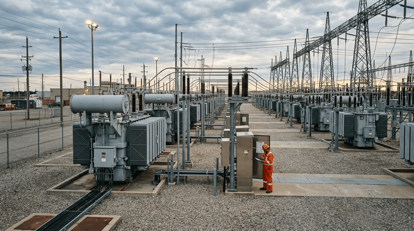
Ambient temperature range and stability directly affects measurement accuracy. Most industrial thermal inspection camera systems specify accuracy at a reference temperature, with performance degrading at extremes. Outdoor installations, furnace-adjacent monitoring points, and cold-storage applications all present conditions where standard commercial specs may not hold. Selecting components with appropriate extended-temperature ratings, and understanding how ambient variation affects accuracy, prevents field performance surprises.
Atmospheric interference is a common source of degraded performance that gets underestimated in the design phase. Steam, dust, particulate-laden air, and chemical vapors all attenuate infrared radiation between the source and the sensor. For applications in steel mills, chemical processing, or cement production, accounting for atmospheric attenuation in field-of-view and placement decisions is essential. Shorter working distances, purged housings, or spectral band selection tuned to the specific atmosphere may all be relevant design choices depending on the application.
Electromagnetic interference affects camera electronics and data transmission in environments with variable-frequency drives, induction furnaces, or high-current switching. Shielded cabling, proper grounding, and appropriate housing specifications are straightforward mitigations — but they need to be in the design, not discovered during site acceptance testing.
Pre-Integration Checklist for OEM Engineering Teams
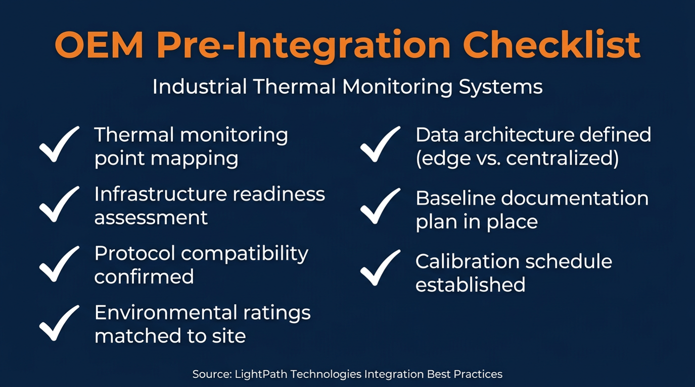
Before component selection is finalized, engineering teams building industrial thermal monitoring systems should confirm the following:
- Thermal monitoring point mapping: All critical monitoring locations identified, with normal operating temperature ranges documented and anomaly thresholds defined
- Infrastructure readiness: Network bandwidth, power availability, and mounting options assessed for each camera location
- Protocol compatibility: Communication standards confirmed against target SCADA, MES, or DCS platforms
- Environmental ratings: IP ratings, temperature range, and vibration specifications matched to actual site conditions
- Data architecture: Edge vs. centralized processing decision made, with storage and alert workflow defined
- Baseline documentation plan: Process established for capturing normal-state thermal profiles before go-live
- Calibration schedule: Initial calibration procedure and ongoing interval defined, with reference instrument access confirmed
Working through this checklist before procurement avoids the scenario where a well-specified thermal inspection camera arrives on-site only to find that the network infrastructure, mounting provisions, or protocol stack wasn't ready for it.
What Are the Key Factors in Choosing an Industrial Thermal Imaging Camera for OEM Integration?
Component selection follows environment planning, not the other way around. With the application requirements clearly defined, the relevant specifications become much easier to evaluate objectively.
The table below maps common industrial thermal monitoring applications to relevant component considerations:
|
Application |
Spectral Band |
Key Considerations |
|
Electrical equipment monitoring |
LWIR (8–14 µm) |
Continuous operation, radiometric accuracy, protocol support |
|
Rotating machinery / bearings |
LWIR (8–14 µm) |
High frame rate, stable calibration, IP-rated housing |
|
High-temp process monitoring (furnaces, kilns) |
MWIR (3–5 µm) |
Extended temp range, atmosphere compensation, ruggedized mount |
|
Gas leak detection (oil and gas) |
Broadband IR (2–14 µm) |
Spectral sensitivity to target gas, outdoor rating |
|
Multi-application / flexible deployment |
BBIR (2–14 µm) |
Broadband coverage, versatile integration options |
Resolution choices follow similar logic. A 320×480 uncooled sensor is appropriate for general equipment monitoring where the goal is detecting relative temperature change over time. Higher-resolution uncooled systems up to 640×480 support more spatially precise monitoring of complex equipment or quality control applications. Cooled systems provide greater thermal sensitivity for long-range or high-precision use cases, though at higher cost, power, and maintenance requirements. For most continuous industrial thermal monitoring applications, uncooled LWIR is the practical choice. Explore LWIR thermal imaging solutions to understand what well-designed uncooled systems can deliver for industrial integration programs.
For applications involving gas detection, broadband IR coverage from 2–14 µm provides the spectral flexibility to capture signatures across a range of gas types and process conditions. The broadband infrared product family addresses this need with purpose-built optical designs for industrial environments.
What Calibration Practices Keep Industrial Thermal Monitoring Systems Accurate Over Time?
Calibration is where thermal monitoring systems either earn long-term operator trust or quietly drift into unreliability. For OEMs building platforms their customers will run for years, calibration discipline is a core part of the system value proposition.
Establishing a Reliable Baseline
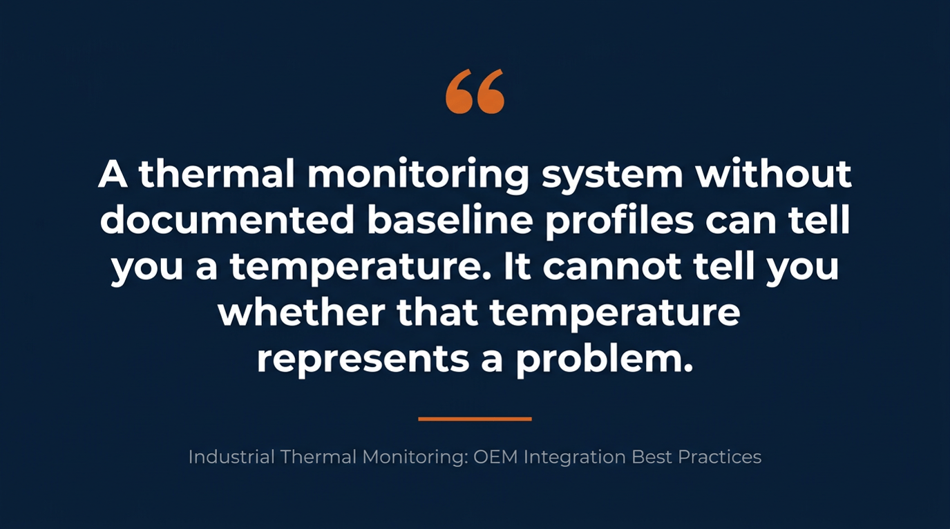
Before a system goes live, establishing comprehensive baseline thermal profiles across all monitored equipment during normal operating conditions is essential. This baseline becomes the foundation for anomaly detection. Without it, the system can detect absolute temperature values but cannot reliably distinguish "warmer than normal" from "operating as expected."
Baseline documentation should capture thermal profiles at representative operating loads, at multiple points in the facility's operating cycle where applicable, and with ambient temperature conditions noted. For electrical equipment monitoring, the 2023 update to NFPA 70B — which moved from recommended practice to mandatory standard and now requires annual infrared thermography inspections for all electrical equipment — makes thorough baseline documentation part of a defensible compliance record, not just a best practice.
Ongoing Calibration Architecture
The table below outlines practical calibration frameworks for different deployment types:
|
Deployment Type |
Calibration Approach |
Recommended Interval |
|
Fixed continuous monitoring (electrical, process) |
Automated drift detection, periodic reference comparison |
Quarterly check, annual full recalibration |
|
Fixed monitoring in extreme environments |
Environmental compensation configuration, more frequent drift checks |
Monthly check, semi-annual recalibration |
|
Mobile / inspection integration |
Pre-deployment reference check, post-campaign comparison |
Before each major campaign |
|
Multi-camera networked systems |
Cross-camera consistency validation, centralized calibration tracking |
Quarterly across system |
Reference instrument cross-validation — comparing thermal camera readings against calibrated contact thermometers or pyrometers at known measurement points — is the practical way to confirm a system is staying within spec. Automated drift detection systems that flag when readings at reference points shift beyond a defined threshold allow maintenance teams to address calibration drift before it affects the quality of data downstream.
Why Does the Thermal Imaging Component Supply Chain Matter to OEM Platform Performance?
The choice of thermal imaging component supplier has downstream effects that extend well beyond initial integration. OEMs building platforms for multi-year production runs need suppliers who can deliver consistent performance across product lots, support engineering changes as the platform evolves, and maintain stable supply of critical optical materials.
Germanium, the traditional material for LWIR optics, has experienced significant supply constraints and pricing volatility. For OEMs building industrial thermal monitoring platforms at volume, a supplier who offers proprietary chalcogenide glass alternatives provides a meaningful supply chain risk mitigation. Components built from alternative optical materials with comparable or superior transmission characteristics reduce exposure to single-source material risk without compromising performance. You can learn more about how infrared optical components and assemblies are engineered for consistent industrial performance.
Vertical integration at the supplier level — where the same manufacturer controls optical design, glass materials, lens production, coatings, and camera assembly — also provides practical advantages for custom OEM programs. When an OEM needs a modified field of view, a different form factor, or a custom interface, a vertically integrated supplier can respond through a single engineering relationship rather than a chain of multiple vendors each managing their own scope.
6 Integration Mistakes That Cause Industrial Thermal Monitoring Programs to Underperform
Even well-resourced OEM programs run into predictable integration issues. The following are the most common:
- Treating protocol selection as a late-stage detail. Communication protocol compatibility with the target control system architecture needs to be confirmed in the system architecture phase. Discovering a mismatch during commissioning is expensive to resolve.
- Under-specifying environmental protection. Selecting a camera housing rated for a clean room and deploying it adjacent to a grinding operation or chemical process is a failure waiting to happen. Match IP and environmental ratings to actual site conditions.
- Skipping baseline documentation. A thermal monitoring system without documented baseline profiles can tell you a temperature — it cannot reliably tell you whether that temperature represents a problem.
- Over-relying on catalog specs without application context. Resolution and sensitivity specifications are measured in controlled conditions. Field performance in a dusty, vibrating, thermally complex environment will differ. Component selection should account for real-world degradation.
- Concentrating all camera placements on known risk points. The most valuable detections are often at locations where failure wasn't anticipated. A thorough thermal mapping exercise before deployment helps identify secondary monitoring value across a facility.
- No structured calibration plan post-deployment. Thermal monitoring systems that drift out of calibration quietly erode operator trust. Building a calibration maintenance program into the system documentation from the start keeps performance where it needs to be.
How Does Industrial Thermal Monitoring Deliver Measurable ROI for OEM Customers?
The business case for thermal monitoring is well-established in the industries OEMs serve. Facilities that implement structured predictive maintenance programs — with thermal imaging as the primary detection layer — consistently report 30–40% reductions in maintenance costs compared to reactive approaches, a figure supported by multiple independent analyses of industrial programs.
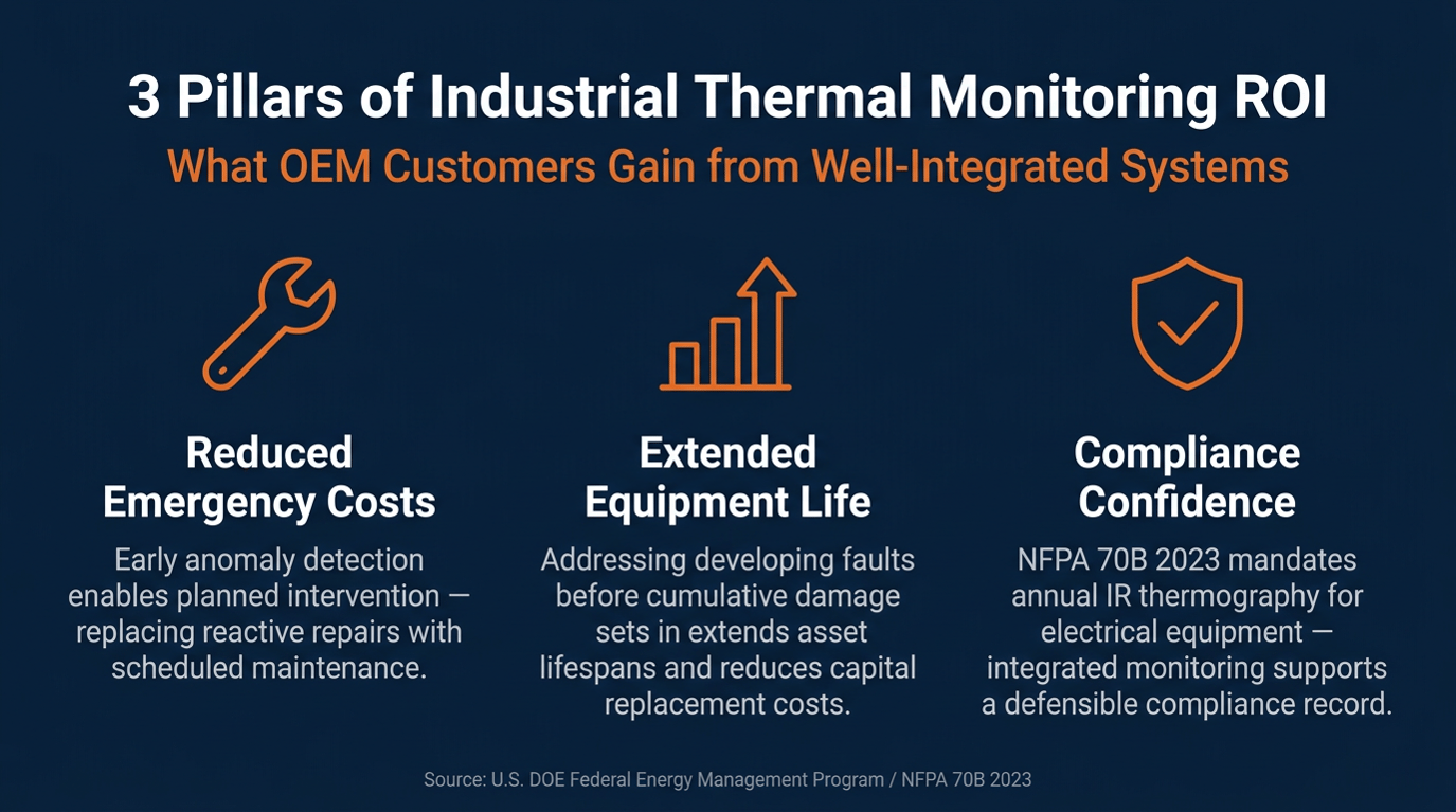
The specific ROI drivers break down across three categories. Reduced emergency maintenance costs come from early anomaly detection that enables planned intervention rather than emergency response — the difference between scheduling a bearing replacement and dealing with an unplanned motor failure mid-shift. Extended equipment lifespan results from addressing developing faults before they cause the cumulative damage that accelerates component wear and degradation. Regulatory compliance value has grown significantly with the 2023 update to NFPA 70B, which created a compliance driver that OEM customers can communicate directly to their facilities teams.
OEMs who build platforms that articulate and support these value drivers in their documentation, training materials, and customer-facing reporting tools give their customers a stronger foundation for justifying the investment and demonstrating results to leadership.
Frequently Asked Questions
What communication protocols should OEMs prioritize for industrial thermal monitoring integration? GigE Vision and USB3 are the standard choices for high-bandwidth thermal video data. For process-level integration with SCADA, MES, or PLC systems, industrial protocols like Modbus TCP, Profinet, and OPC-UA provide the interoperability that industrial deployments require. The right combination depends on the target control architecture, which is why protocol selection needs to happen at the system design stage.
What's the difference between LWIR and BBIR for industrial thermal monitoring applications? LWIR (8–14 µm) is the workhorse band for most industrial thermal monitoring — electrical inspection, rotating machinery, and general equipment health monitoring. Broadband IR (2–14 µm) provides spectral flexibility for applications where you need sensitivity across a wider range of emission signatures, including certain gas detection and high-temperature process applications. Most continuous industrial monitoring platforms use LWIR for its combination of performance and cost efficiency.
How often do industrial thermal monitoring systems need to be recalibrated? For most fixed continuous monitoring installations, a quarterly drift check combined with an annual full recalibration against reference instruments is a practical baseline. Applications in extreme environments — high-temperature processes, outdoor installations subject to wide seasonal swings — may require more frequent intervals. The 2023 update to NFPA 70B also introduces documentation requirements for electrical thermography that effectively define a minimum compliance-driven inspection schedule for that application category.
What makes vertical integration important when selecting a thermal imaging component supplier for OEM programs? When the same supplier controls optical materials, lens design, coatings, and camera assembly, they can optimize the system as a whole rather than assembling independently specified parts. For OEM programs that require customization — modified fields of view, specific form factors, or interface variations — a vertically integrated supplier can execute those changes through a single engineering relationship, which is faster and more reliable than coordinating across multiple vendors.
Ready to Build a More Competitive Industrial Thermal Monitoring Platform?
Industrial thermal monitoring is a systems engineering challenge that rewards careful upfront planning, disciplined component selection, and a supplier relationship that can support the program as requirements evolve. The platforms that outperform over time are the ones where the thermal imaging components were selected and integrated as part of a thoughtful architecture — not specified in isolation and assembled at the end.
For OEMs and system integrators looking to build industrial thermal monitoring platforms with the optical precision, supply chain reliability, and custom engineering capability to compete in demanding markets, LightPath Technologies brings four decades of infrared optics and thermal imaging experience to every program. Reach out to the engineering team at LightPath to start the conversation.