
Key Takeaways
Optical gas imaging helps you find hazardous and valuable gas emissions before they become larger safety, environmental, or production problems.
- A VOC leak detection camera uses specialized infrared wavelengths to reveal gas plumes that ordinary vision cannot detect.
- Non-contact imaging can support inspections without equipment shutdowns or unnecessary worker exposure.
- Camera selection depends on gas sensitivity, spectral response, optics, detector architecture, and operating conditions.
- Fixed, vehicle-mounted, drone-based, and handheld systems can support different inspection patterns.
- A successful program connects imaging with verification, repair prioritization, documentation, and long-term monitoring.
Understand how a VOC leak detection camera works
A gas leak can remain invisible while still creating a serious operational risk. Optical gas imaging gives you a way to observe emissions remotely, turning an otherwise hidden event into a visual signal that inspectors and monitoring systems can evaluate. The method is especially useful where process equipment is extensive, access is restricted, or interruption would be costly. Understanding the underlying imaging process helps you specify a system that fits the gases and conditions you actually need to monitor.
What volatile organic compounds are and why leaks are difficult to see
Volatile organic compounds, or VOCs, are carbon-based chemicals that can evaporate into the air under ordinary operating conditions. Industrial facilities may handle hydrocarbons and other compounds in pipes, vessels, compressors, storage systems, and process equipment. A leak may disperse quickly, have no visible color, and occur at a connection that is difficult to approach safely. Ambient light and ordinary video therefore provide little dependable evidence of the release.
The challenge is not limited to finding a damaged component. Wind, temperature contrast, background movement, and changing process conditions can alter the appearance and direction of a plume. An inspection method must help you distinguish a real release from normal scene variation while preserving enough detail to trace the plume back toward its source.
How optical gas imaging makes invisible plumes visible
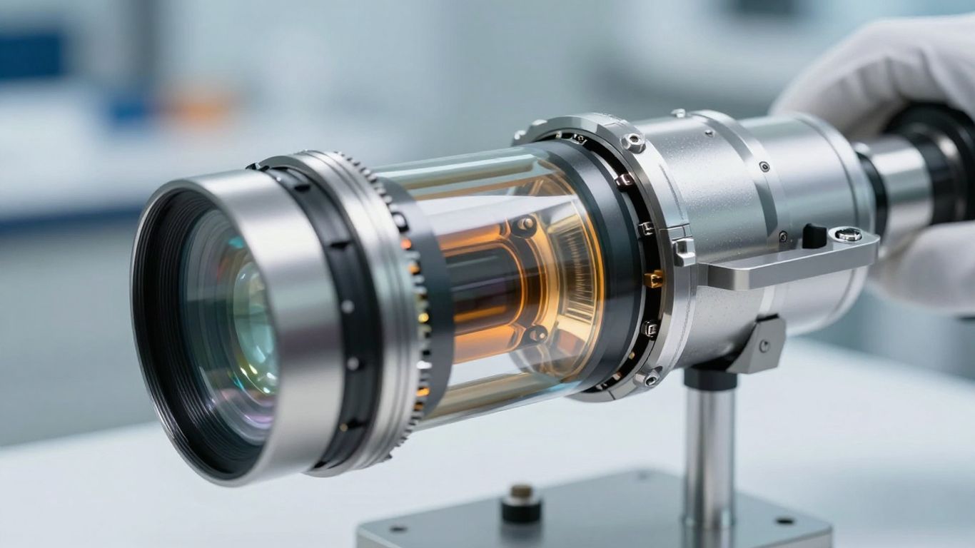
Optical gas imaging cameras use an infrared detector and optical filtering selected for the absorption behavior of a target gas. When the gas passes through the camera’s field of view, it changes the infrared energy reaching the detector. Processing then displays that difference as a moving plume against the surrounding equipment and background.
This is an imaging method rather than a single-point sample. You can scan a group of valves, flanges, seals, or other components and watch the plume respond as conditions change. MWIR camera systems are commonly discussed for this application because the mid-wave infrared band includes wavelengths where many methane and hydrocarbon gases absorb energy.
The role of infrared wavelengths in methane and hydrocarbon detection
The spectral response is central to performance. Methane and other hydrocarbons interact with particular infrared wavelengths, so a detector and filter must be matched to the gases of interest rather than selected only by visible-image resolution. Mid-wave infrared systems are often suitable for methane and light hydrocarbons, while other compounds may require a different spectral approach.
You should also consider the scene itself. Atmospheric path length, background temperature, plume concentration, distance, and wind can affect contrast. A camera that performs well in a controlled demonstration may need different optics, calibration practices, or operating limits when deployed across a large outdoor facility.
How real-time imaging compares with traditional leak inspection methods
Traditional inspections may rely on contact instruments, handheld probes, soap solutions, or scheduled walkdowns. These methods remain useful for confirmation and quantification, but they can require close access and may examine one component at a time. Real-time imaging lets you survey a broader view from a distance and observe the movement of a plume as it forms.
That difference changes the workflow. You can use imaging to locate and prioritize a suspected source, then apply a complementary measurement tool to confirm the finding and support repair records. For a practical overview of the inspection model, thermal imaging leak detection offers additional background on remote visualization and documentation.
Identify the operational benefits of optical gas imaging
Optical gas imaging is valuable because it connects detection with practical plant operations. You can inspect equipment while it is running, keep personnel farther from a suspected release, and cover areas that would otherwise take considerable time to access. The method does not eliminate the need for procedures or confirmatory measurements, but it can make the first stage of leak response faster and more informed.
Detect leaks without direct contact or equipment shutdowns
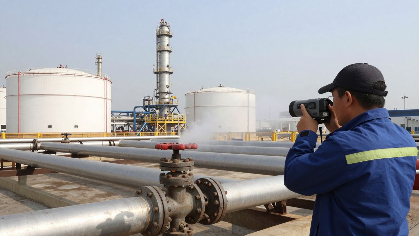
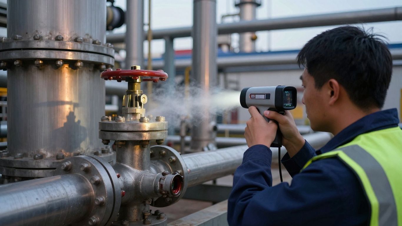
A non-contact camera can observe process equipment from an appropriate standoff distance. That allows you to inspect operating assets without placing a probe against every connection or stopping a process solely for a visual search. For facilities where production continuity matters, the ability to survey during normal operation can improve the timing and practicality of inspections.
The camera does not need physical contact with the pipe, flange, valve, or vessel. Instead, the operator positions the scene within the field of view and looks for a plume consistent with the target gas and current conditions. A suspected location can then be examined more closely using an approved verification method.
Improve worker safety around hazardous process areas
Distance can reduce exposure to hazardous process areas, hot surfaces, pressurized equipment, and difficult access points. It does not replace hazard assessment, personal protective equipment, or site rules. It gives your team another way to gather useful information before deciding whether close access is necessary.
The safest workflow treats the image as an early observation, not an automatic diagnosis. Operators should understand camera limitations, maintain safe standoff distances, and coordinate findings with the facility’s permit, isolation, and emergency procedures.
Survey large facilities and remote infrastructure more efficiently
Large plants and distributed assets create a coverage problem. A handheld inspection may require repeated walks, while remote pipelines and difficult terrain can make routine access slow or expensive. Vehicle-mounted and drone-based imaging can extend the survey area, provided the platform, weather limits, flight rules, and image quality are appropriate.
An efficient program normally combines broad screening with focused follow-up. The initial pass identifies unusual plume activity; a closer inspection then narrows the source and determines the next measurement. This approach helps you spend specialist time where the visual evidence suggests the greatest need.
Reduce emissions, product loss, and unplanned downtime
A leak can waste saleable material, contribute to emissions, and signal a developing equipment problem. Finding it earlier gives maintenance and operations teams more opportunity to plan a repair instead of waiting for a larger release or an unexpected interruption. The financial and environmental value depends on the asset, gas, leak rate, and response quality, so results should be measured within your own program.
A useful field review usually records the observed location, operating state, weather, image conditions, verification result, repair action, and follow-up status. Those records help you connect detection activity with actual improvements rather than treating camera availability as the outcome itself.
Use VOC imaging across industrial environments
A VOC imaging program should follow the assets and risks of your operation. Upstream facilities may prioritize well sites and separators, midstream operators may focus on pipelines and compression, and downstream plants may need dense inspection around processing equipment. The same imaging principle can support each setting, but optics, mounting, certification, weather protection, and inspection distance may differ considerably.
Monitor upstream, midstream, and downstream oil and gas assets
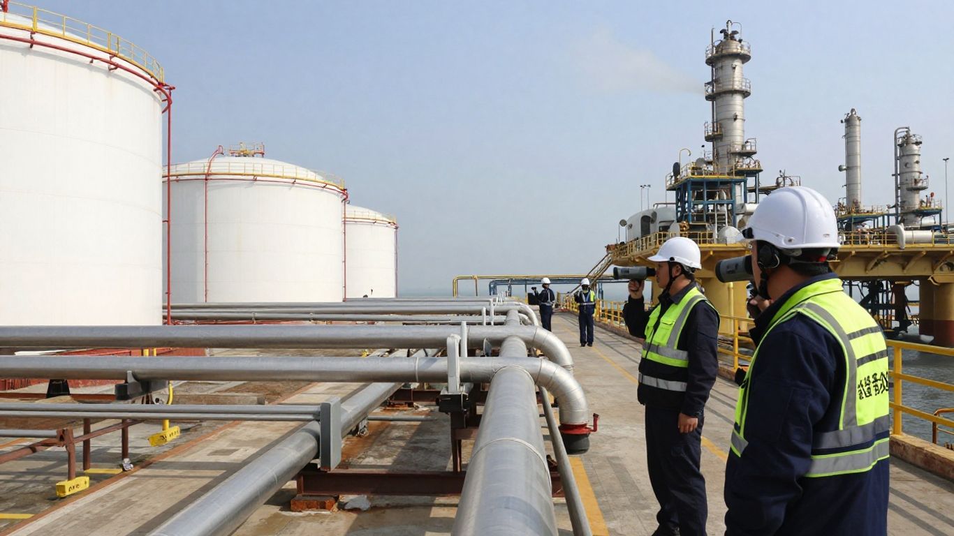
Upstream operations may use optical gas imaging around production equipment, gathering systems, and well-site infrastructure. Midstream teams can apply it to compressor stations, transfer points, and pipeline corridors. Downstream facilities often need frequent surveys around storage, processing, loading, and recovery systems.
LightPath provides optical gas imaging cameras engineered to detect methane and other hydrocarbons in real time, with high sensitivity and consistent performance for environmental monitoring and industrial safety. The documented scope also includes support for OEM systems intended for upstream, midstream, and downstream environments, making system definition an important part of the project.
Inspect refineries, chemical plants, and processing facilities
Refineries and chemical plants combine dense equipment, elevated temperatures, restricted areas, and potentially hazardous atmospheres. A camera can help you screen piping runs and process units without bringing an inspector immediately beside every component. It can also support continuous monitoring concepts in locations where periodic manual inspection leaves long gaps.
The gas list and spectral band should be established before procurement. A system suited to methane is not automatically suited to every VOC, and a broad product description should not substitute for application-specific sensitivity data. Your engineering team should define the gases, distances, backgrounds, and operating conditions that matter most.
Survey pipelines, storage tanks, valves, and flanges
Leaks often originate at interfaces: seals, fittings, valves, flanges, tank connections, and transfer equipment. These locations can be numerous and spread across an extensive site. Imaging helps you search the surrounding scene first, then move toward the likely source instead of checking every component with equal intensity.
For pipeline surveys, the platform determines much of the inspection pattern. A handheld system may suit a station walkdown, while a vehicle or drone can cover a corridor. Storage tanks and elevated flanges may require longer-range optics, stable mounting, or an access plan that accounts for wind and changing backgrounds.
Support offshore platforms and other harsh-environment operations
Offshore and remote sites expose imaging equipment to saltwater, vibration, temperature changes, dust, and difficult maintenance access. The camera housing, optics, electronics, mount, and connectors must be considered as one deployment rather than as unrelated parts. A system that maintains image quality but cannot tolerate the environment is not a reliable monitoring asset.
LightPath describes its optical and infrared imaging systems as supporting oil and gas operations from offshore platforms to refineries, with designs intended for demanding conditions. That positioning is most relevant when you are defining an OEM platform and need the optical subsystem, detector integration, filtering, coatings, and environmental requirements considered together.
Choose the right camera for reliable leak detection
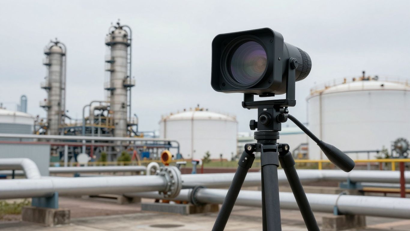
Selecting a VOC camera is an application exercise, not a resolution contest. You need to match the detector and optical path to the gas, distance, background, weather, and inspection method. The system should also produce imagery that operators can interpret consistently and that engineering teams can integrate into a broader platform.
Evaluate gas sensitivity and minimum detectable leak rates
Sensitivity should be expressed in terms that relate to the intended inspection: target gas, distance, temperature difference, wind, background, and minimum detectable leak rate. Ask how the value was established and whether the test conditions resemble your facility. A nominal sensitivity figure without its measurement context can lead to an unrealistic expectation in the field.
You should also separate detection from quantification. Seeing a plume can identify a suspected leak, while estimating or measuring its rate may require additional analytics, calibration, or a secondary instrument. Define which result your compliance and maintenance workflow actually requires.
Match infrared spectral response to methane and other VOCs
Start with a gas inventory. Methane, light hydrocarbons, and other VOCs have different infrared absorption characteristics, so the camera’s spectral response must align with the compounds you need to observe. If several gases matter, evaluate whether one system covers the required range or whether different optical configurations are more appropriate.
The V340 OGI camera is an example of a system described with a 3.2 to 3.5 μm spectral range and detection of more than 400 VOCs. Those details belong to that documented product description; they should not be generalized to every optical gas imaging camera or treated as a universal specification.
Compare cooled and uncooled camera architectures
Cooled detectors can provide high sensitivity and strong performance for demanding applications, while uncooled architectures can reduce system complexity, power requirements, size, and maintenance needs. The better choice depends on the required detection performance, operating distance, platform constraints, and environmental design.
For OEMs, detector architecture affects more than the camera core. It influences power, thermal management, startup behavior, housing volume, service access, and the total integration schedule. Compare the complete system rather than selecting a detector in isolation.
Consider resolution, field of view, zoom, and inspection distance
Resolution determines how much spatial detail you can preserve, but field of view determines how much equipment you can see at once. Zoom can help you move from facility-level screening to component-level examination, while the optical design determines whether that detail remains useful at the working distance.
LightPath’s cooled zoom cameras are documented for applications where distance and detail matter, with system-level design that includes cold-shield efficiency and optical coatings. In a gas-imaging application, you should confirm that the proposed optical configuration is matched to the detector, filter, target gas, and expected inspection range.
Assess false alarms, image clarity, and measurement repeatability
A clear plume image is useful only when operators can distinguish it from glare, heat shimmer, dust, steam, moving vegetation, or other scene effects. Test the camera across representative backgrounds and operating states. Repeatability matters as well: the same asset should produce interpretable results when inspected by different people or under modestly changing conditions.
LightPath describes its optical gas imaging cameras as providing high sensitivity and consistent performance while minimizing false alarms. Your acceptance testing should still define the conditions, alarm logic, image records, and verification process used to judge that performance in the finished system.
Design for safety, compliance, and harsh conditions
A camera used around hydrocarbons or chemical processes must fit the site’s safety framework as well as its imaging task. Hazardous-area requirements, environmental sealing, calibration, data records, and operator training all influence the final design. Treating these factors as late-stage accessories can create delays or force compromises after the main hardware has already been selected.
Select equipment for hazardous-area and explosion-protection requirements
Begin with the area classification, gas group, temperature class, installation location, and operating procedure. Determine whether the complete camera assembly, housing, mount, power system, and communications path satisfy the required protection approach. Certification is not a generic label; it must match the actual deployment and jurisdiction.
Where certification is unavailable for the intended platform, you may need a protected installation arrangement or a different inspection workflow. The decision should be made with site safety personnel and the responsible engineering authority before field deployment.
Protect cameras from heat, vibration, dust, moisture, and chemical exposure
Industrial conditions can degrade optical elements, corrode housings, loosen mounts, and stress electronics. Offshore saltwater, process heat, dust, vibration, and thermal cycling each create different failure modes. Specify enclosure materials, seals, windows, mounts, cable routing, and service intervals together.
The optical path deserves particular attention. A housing may survive the environment while a window accumulates contamination or an optical element shifts under temperature. System-level environmental testing is more informative than a component rating considered on its own.
Maintain calibration accuracy across changing temperatures
Temperature changes can affect detector response, optics, electronics, and the apparent contrast between a plume and its background. Calibration procedures should define when checks occur, which reference conditions are used, and how drift is recorded. You should also understand how the system behaves during startup, warm-up, and transitions between indoor and outdoor environments.
A stable result is not simply a factory specification. It depends on the camera, optical filtering, housing, software, mounting arrangement, and field procedure operating as intended. This is one reason matched system design can be valuable in an OEM program.
Document inspections for leak detection and repair programs
Documentation turns an observation into an actionable record. Capture the asset identifier, location, date, operator, gas or process context, weather, viewing distance, image sequence, verification result, repair decision, and follow-up date. Consistent naming and storage make it easier to compare inspections over time.
Your records should support both compliance and maintenance. A plume image can show why a work order was created, while the follow-up inspection can establish whether the repair resolved the suspected source. The program should define retention, access, review, and escalation rules before inspections begin.
Balance continuous monitoring with portable inspection workflows
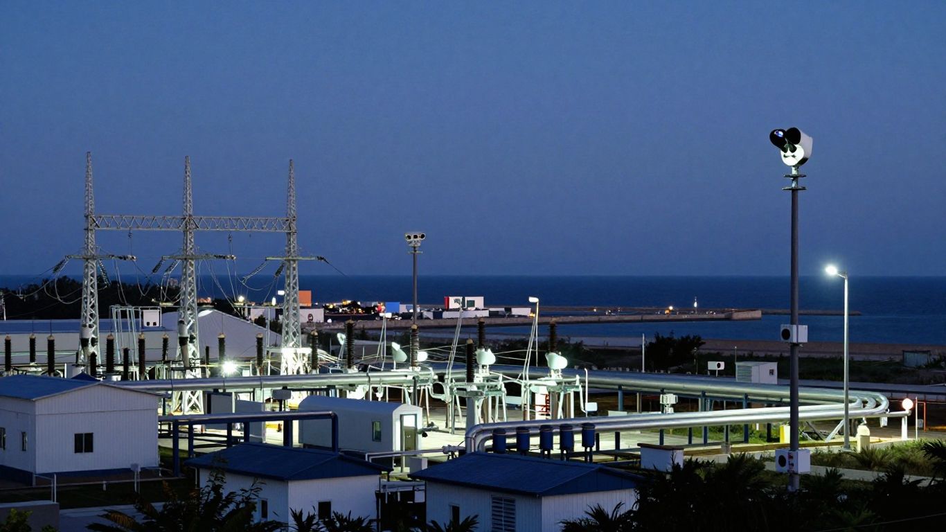
Fixed cameras can watch priority areas continuously and send alerts to an operating team. Portable cameras offer flexibility for route-based surveys, troubleshooting, commissioning, and follow-up. Many facilities need both approaches because not every asset has the same consequence, access pattern, or monitoring frequency.
Use risk to decide where continuous coverage adds value. Reserve portable inspections for broad surveys and changing priorities, then adjust fixed-camera placement as your findings reveal recurring sources or blind spots. This creates a practical balance between coverage and cost.
Integrate VOC cameras into industrial monitoring systems
An imaging camera becomes more useful when its output fits the way your facility already works. Operators need understandable alerts, maintenance teams need traceable records, and engineers need stable interfaces and predictable data. Integration should therefore be planned alongside optical performance rather than after the camera has been chosen.
Connect camera outputs to control rooms and video management platforms
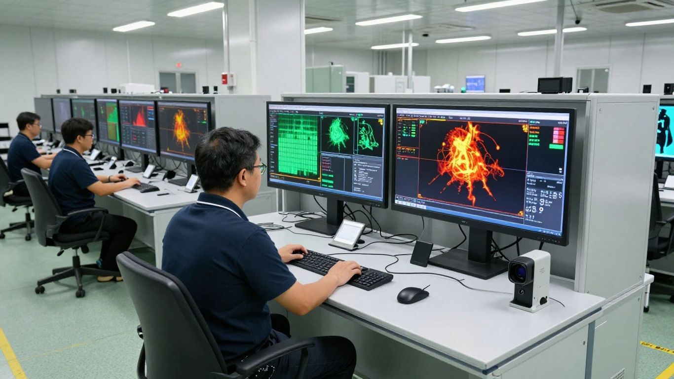
Define how live video, event clips, alarms, metadata, and health status will reach the control room or video management platform. Consider latency, network reliability, cybersecurity, user permissions, and what happens when communications are interrupted. A clear interface reduces the chance that a useful detection is lost among unrelated notifications.
Alarm presentation also matters. Operators should be able to identify the camera, asset, time, suspected location, and current image without searching through disconnected systems. Test the complete path from plume observation to operator acknowledgement and maintenance handoff.
Use edge processing and AI to prioritize suspected leaks
Edge processing can reduce bandwidth and support quicker local decisions. Analytics may identify changing plume patterns, compare a scene with prior imagery, or prioritize alarms for human review. These tools should assist inspection rather than conceal uncertainty behind an automated label.
Set thresholds using representative data and review false positives after deployment. The best alert is one that directs attention to a credible event while retaining the image and context needed for a person to make the final operational decision.
Combine optical gas imaging with visual and thermal sensors
Visible video can provide scene context, while thermal imaging can reveal temperature differences and equipment conditions. Optical gas imaging addresses a different question: whether a target gas is altering the infrared signal in the selected spectral band. Combining the sensors can help operators locate an asset, interpret its operating state, and investigate a suspected release.
The streams should be time-aligned and spatially registered where practical. Otherwise, teams may spend time reconciling separate views instead of responding to the event. A shared asset model and consistent timestamps are small design choices with large operational value.
Deploy cameras on fixed mounts, vehicles, drones, or handheld systems
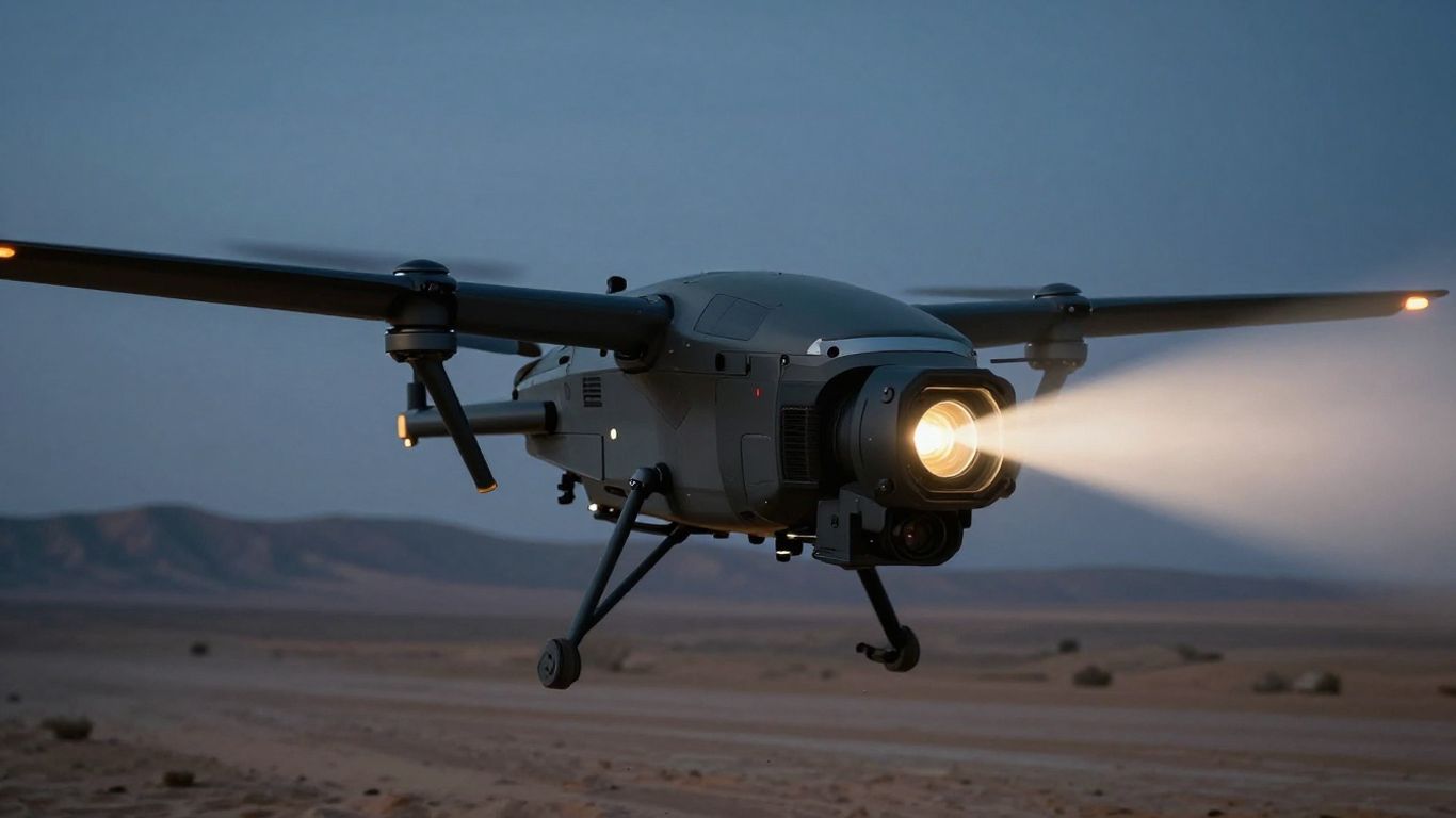
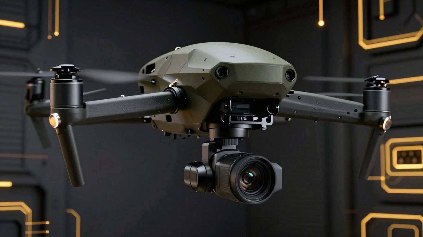
The platform determines mobility, power, vibration, viewing angle, and operator involvement. Fixed mounts suit priority areas and continuous observation; vehicles can cover roads and pipeline corridors; drones can reach difficult terrain; handheld units support close survey work and verification.
Each platform also changes the evidence you collect. A fixed camera can build a time history, while a handheld inspection may capture more varied viewpoints. Select the platform according to the asset map and response workflow, not simply the novelty of the deployment method.
Plan optics, interfaces, power, and environmental protection during OEM integration
OEM integration should define the optical aperture, filter requirements, detector interface, processing hardware, power budget, mounting envelope, thermal management, communications, and enclosure. These decisions interact. A small change in field of view can affect lens size, image detail, housing dimensions, and the mechanical load on the mount.
LightPath works with program leads to define performance specifications, integrate systems into platforms, and validate results before deployment. That partnered development model is relevant when your project requires an optical and infrared subsystem shaped around a particular industrial platform rather than a disconnected catalog component.
Build a faster and safer leak response process
Detection is only the beginning of leak management. Your program needs a repeatable path from inspection planning to confirmation, repair, verification, and trend review. When those steps are defined in advance, an image can prompt a coordinated response instead of creating another unresolved item in the maintenance queue.
Establish inspection routes and monitoring intervals
Map assets by gas, process pressure, access difficulty, consequence, and history. Use that map to set route frequency for portable surveys and observation intervals for fixed cameras. Higher-consequence equipment may need continuous monitoring or shorter inspection cycles, while lower-risk areas can follow a periodic route.
Document why each interval was selected and revisit it after findings, process changes, or repairs. A route that made sense during commissioning may not remain appropriate after production capacity, equipment layout, or regulatory expectations change.
Confirm suspected leaks with complementary measurement tools
Optical gas imaging can locate a suspected plume, but confirmation may require a contact instrument, sampling method, acoustic technique, or another approved measurement. Use the tool that matches the required decision: repair authorization, emissions estimation, safety escalation, or regulatory reporting.
The confirmation procedure should preserve the connection between the image and the measured result. Record the component, conditions, instrument, operator, and result so that later reviewers can understand how the decision was reached.
Rank repairs by safety, environmental, and production impact
Not every visible indication carries the same consequence. Prioritize the release that creates the greatest immediate hazard, environmental concern, product loss, or risk of process interruption. Include access conditions and repair complexity, since an apparently small leak in a difficult location may deserve a different plan from a larger but easily isolated release.
A clear ranking process helps operations, safety, environmental, and maintenance teams work from the same information. It also makes resource decisions easier to explain when several findings appear during one survey.
Track repair verification and long-term emissions performance
Close the loop with a post-repair inspection. Compare the original image, repair record, confirmation result, and follow-up image under reasonably comparable conditions. If the plume remains, the source may have been misidentified, the repair may be incomplete, or a nearby component may be contributing to the observation.
Over time, your records can reveal recurring equipment types, process states, weather effects, and locations. That information supports better inspection intervals and more targeted engineering changes, while keeping the distinction clear between a detected event and a verified improvement.
Specify a reliable imaging partner for custom industrial platforms
For a custom system, assess the partner’s ability to address optics, infrared components, detector integration, filtering, coatings, electronics, environmental design, manufacturing, and validation as connected requirements. Ask how performance specifications will be translated into a tested assembly and how changes will be managed through production.
LightPath offers optical gas imaging, broadband infrared, and long-range system integration capabilities for OEMs, with in-house manufacturing of critical thermal components described in its technical materials. If your program needs a tailored imaging subsystem, plan your next discussion around the gases, distances, platform limits, environmental conditions, and records your users require.
Contact the Imaging Team
Discuss your industrial imaging requirements with LightPath engineers and outline the performance, integration, and environmental conditions your platform must meet. Visit https://www.lightpath.com/contact to contact the team and begin a focused technical conversation.
Conclusion
A VOC leak detection camera can make hidden emissions visible while equipment remains in service, but reliable results depend on more than the detector. Gas-specific spectral design, suitable optics, safe deployment, environmental protection, verification, and disciplined response procedures must work together. When you treat imaging as part of a complete monitoring system, you can turn earlier detection into safer inspections and more deliberate maintenance decisions.
Frequently Asked Questions
What is a VOC leak detection camera?
It is an infrared imaging system designed to visualize gas emissions that are difficult or impossible to see with ordinary cameras. The camera detects changes in infrared energy associated with gases in its selected spectral range.
Can optical gas imaging detect methane?
Yes, optical gas imaging systems can be designed to detect methane when their detector, filters, optics, and operating conditions are appropriate for methane absorption characteristics. Always verify the stated performance for the intended distance and environment.
Does optical gas imaging require equipment shutdown?
Typically, imaging is a non-contact inspection method that can observe operating equipment. Site procedures may still require isolation, shutdown, or additional controls for confirmation and repair.
Can one camera detect every VOC?
No. Different compounds absorb infrared energy differently, and cameras have specific spectral responses. You should match the system to the gases in your process and confirm the manufacturer’s documented detection scope.
How does optical gas imaging differ from a gas detector?
A gas detector may sample or measure gas concentration at a point, while optical gas imaging shows a plume across a scene. The two methods can complement each other: imaging can help locate a suspected source, and a detector can support confirmation or measurement.
What affects leak visibility in an infrared image?
Gas concentration, distance, wind, background temperature, atmospheric conditions, camera sensitivity, spectral response, focus, and operator technique can all affect visibility. Testing under representative conditions is essential.
Should imaging results be verified before repair?
Yes. A suspected plume should normally be confirmed using a suitable complementary measurement or approved procedure before the result is used for repair, reporting, or emissions quantification.